What is a differential pressure transmitter? How DP measurement works
DWIN Engineering, , 7 min read
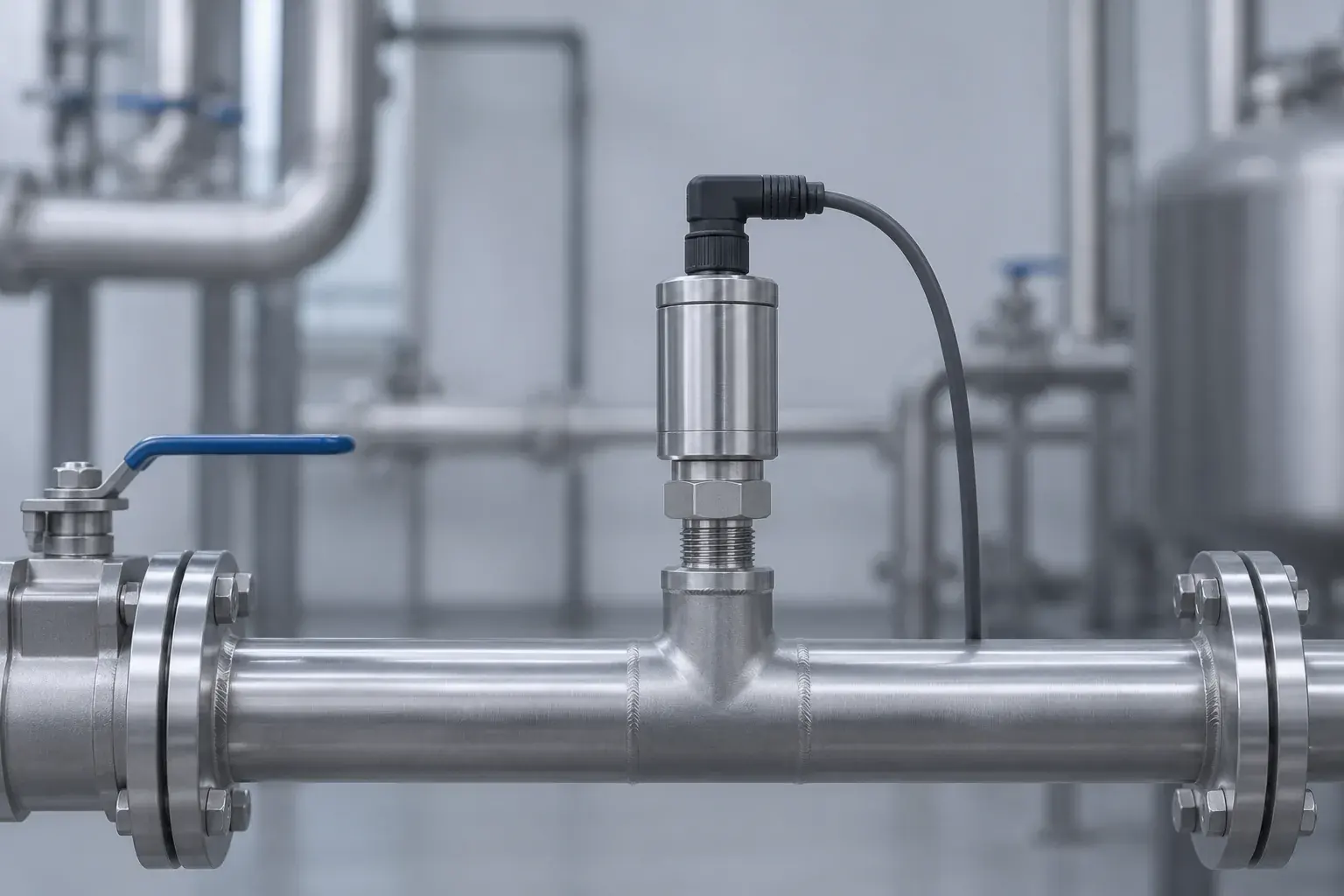
A differential pressure (DP) transmitter has two pressure ports, high (H) and low (L), and outputs a signal proportional to the difference between them, ΔP = P(H) − P(L). It is used to watch filters clog, to measure flow across an orifice or venturi, and to measure level in closed or pressurized tanks.
How does a differential pressure transmitter work?
Inside the transmitter, one sensing element sees the high-side pressure on one face and the low-side pressure on the other. It responds only to the difference, so if both ports rise by the same amount, the output does not change.
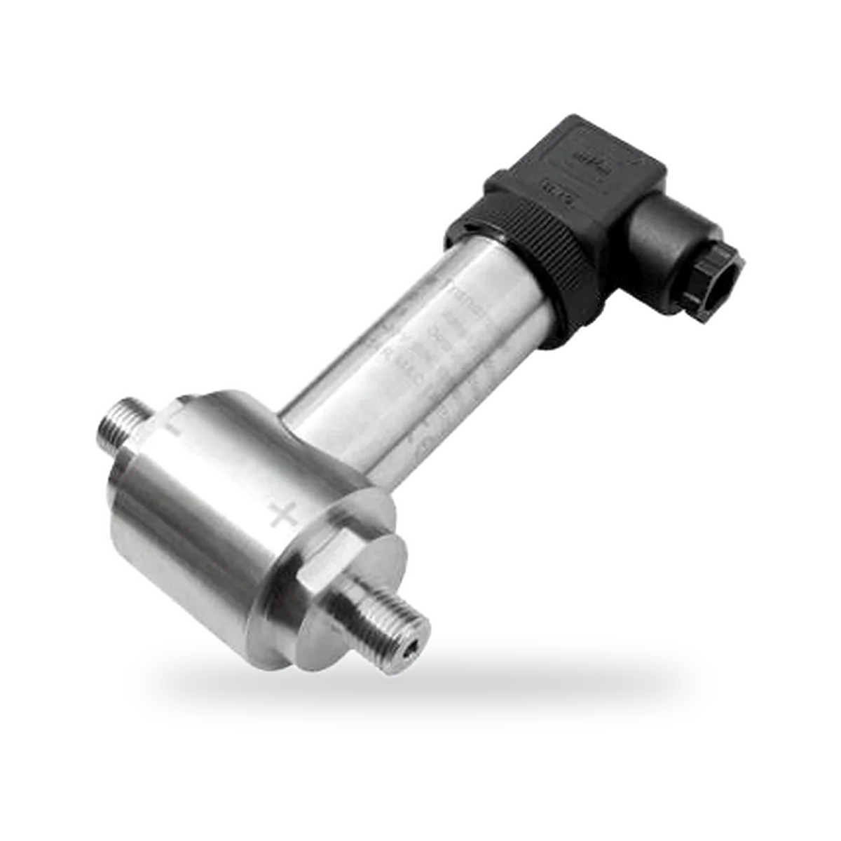
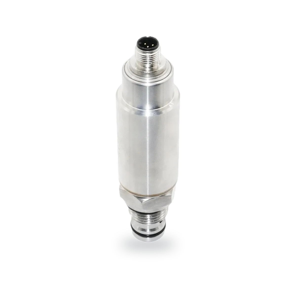
In DWIN's CS-PT500 the element is a diffused silicon chip in an oil-filled core: a 316L stainless steel isolation diaphragm keeps the process medium away from the chip, and the oil passes the pressure through to it. The CS-PT506 uses a solid-state piezoresistive chip, also behind 316L isolation diaphragms. In both, the electronics compensate for temperature and output 4 to 20 mA across the calibrated differential range.
What is static pressure, and why does it matter?
Static pressure, also called line pressure, is the pressure both ports share. A filter in a 10 bar water line might have a pressure drop of only 0.3 bar: the static pressure is about 10 bar, the differential pressure 0.3 bar. The transmitter must survive the 10 bar on both sides while resolving the 0.3 bar between them.
Datasheets give a maximum static pressure separately from the differential range. Both DWIN models allow up to 20 MPa static pressure. For the CS-PT500, DWIN asks you to consult it when the ratio of static to differential pressure is greater than 10, because a very small difference on a very high line pressure needs a matched choice of range.
The overload rating is a separate limit. It is the largest pressure difference the cell tolerates, for example when one port is open and the other sees full line pressure. The CS-PT506 has a 0 to 5 bar range and an overload of 14 bar, so even though it can sit at 20 MPa static pressure, one side must never see much more than 14 bar above the other.
Filter monitoring
As a filter loads with dirt, the pressure drop across it rises. A DP transmitter with H before the filter and L after it turns that rise into a trend, so maintenance can change the filter on condition instead of on a calendar, and an alarm can fire before the filter collapses or bypasses. The same method checks strainers, heat exchangers and membranes.
Flow measurement with an orifice plate or venturi
A restriction in a pipe, such as an orifice plate, venturi or flow nozzle, makes the fluid speed up and its pressure fall. The flow rate is proportional to the square root of the pressure drop: Q = k√ΔP, where k depends on the restriction, pipe and fluid.
The square root has a practical effect. At half of full flow the differential pressure is only a quarter of full scale, and at 10% flow it is 1%. Readings at low flow are therefore less precise, and the controller or transmitter must apply square-root extraction to show flow rather than pressure. DWIN lists flow measurement among the applications of the CS-PT500.
Level in closed and pressurized tanks
In an open tank a single gauge transmitter at the bottom measures level. In a closed tank, the gas pressure above the liquid adds to the reading. Connecting the H port to the bottom of the tank and the L port to the gas space cancels the gas pressure, leaving ΔP = ρgh, the liquid column alone.
If the low-side line can fill with condensate, the level reading shifts. Either keep that line dry and drained (a dry leg), or fill it on purpose with a known liquid (a wet leg) and correct for the column it adds. The same DP principle measures the water level difference across a dam or sluice, one of the applications DWIN gives for the CS-PT500.
DWIN differential pressure transmitters
| CS-PT500 | CS-PT506 | |
|---|---|---|
| Differential range | 0–5 kPa to 0–2,000 kPa | 0–5 bar |
| Maximum static pressure | 20 MPa | 20 MPa |
| Overload | ≥150% FS | 14 bar |
| Accuracy | ±0.5% FS | ±0.5% |
| Output and supply | 4 to 20 mA, 10 to 30 VDC | 4 to 20 mA, 10 to 30 VDC |
| Process connection | G1/4 | G1/2 external thread |
| Electrical connection | DIN 43650A, IP65 | M12, IP65 |
| Operating or medium temperature | −20 to 105 °C operating | −20 to 125 °C medium, no freezing |
| Notes | Intrinsically safe version to GB 3836.4 | Non-corrosive liquids and gases, 304 or 316L housing |
How to install a differential pressure transmitter
- Connect the higher pressure to the H port: upstream of a filter or orifice, or the bottom of a tank
- For liquids, mount the transmitter below the pressure taps so gas bubbles rise back into the pipe
- For gases, mount it above the taps so condensate drains back into the pipe
- Run both impulse lines side by side, at the same temperature and with a steady slope, without high or low pockets
- Fit a three-valve manifold so the transmitter can be isolated and zeroed in service
- When putting it into service, open the equalizing valve first, then the high and low valves, then close the equalizing valve, so one side never sees the full line pressure alone
- Zero the transmitter at working static pressure with the equalizing valve open
How to choose a differential pressure range
Start from the largest difference you need to read: the alarm pressure drop of a dirty filter, the ΔP at maximum flow, or ρgh at the highest level. Pick the range just above it, then check that the static pressure stays within 20 MPa and that the worst one-sided pressure stays below the overload rating. Finally, confirm that the wetted materials suit the medium: the CS-PT506 is specified for non-corrosive liquids and gases.
Frequently asked questions
What does a differential pressure transmitter measure?
It measures the difference between the pressures at its high (H) and low (L) ports, not the pressure in either one. That difference indicates a clogging filter, the flow through an orifice plate, or the liquid level in a closed tank. The output, usually 4 to 20 mA, is proportional to that difference across the calibrated range.
What is the difference between a differential and a gauge pressure transmitter?
A gauge pressure transmitter measures one pressure relative to the surrounding atmosphere. A differential transmitter measures one process pressure relative to another process pressure. A gauge transmitter is in effect a differential one whose low side is open to air.
How do you calculate flow from differential pressure?
Flow through an orifice plate, venturi or nozzle is proportional to the square root of the differential pressure: Q = k√ΔP. The constant k comes from the restriction size, the pipe and the fluid density. Because of the square root, 50% flow gives only 25% of the full-scale differential pressure.
What happens if you connect the high and low ports backwards?
The transmitter sees a negative difference, so a standard 0-based range reads at or below 4 mA and the process looks empty or stopped. It is not usually damaged as long as the difference stays within the overload rating. Swap the impulse lines or reconnect at the manifold to fix it.
What is a three-valve manifold for?
A three-valve manifold has an isolation valve for each port and an equalizing valve between them. It lets you isolate the transmitter, equalize both sides to check the zero at line pressure, and bring the transmitter into service without applying full line pressure to one side only.